 |
 |
 |
|---|
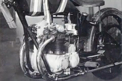
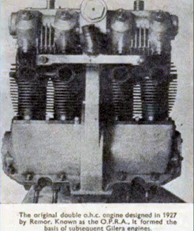
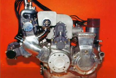
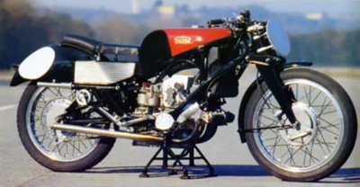
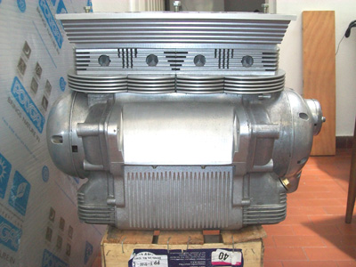
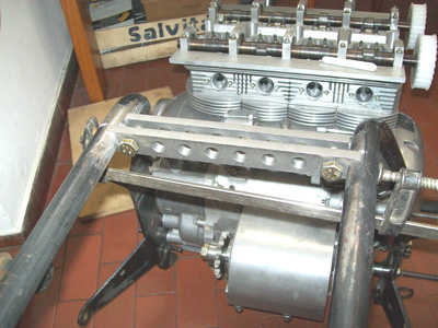
All the job done on the 300 and later at the 150 , couldn't calm my ansiety . I'd continue looking and studying what the "Ingeniere" from Gilera have done with the development of the G.B.A. from 1923 , the O.P.R.A. from 1927 , the Rondine from 1938 , until the "Quattro" from 1957 , really superlative !
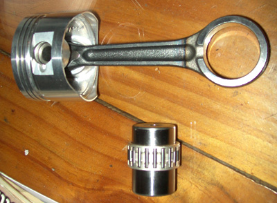
One of the best presents got at my birthday came from my friend Adrian , who appears to me with complete set of connecting rod and piston as gift . |
|---|
 |
|---|
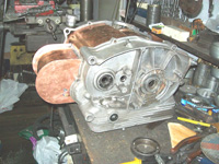
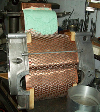
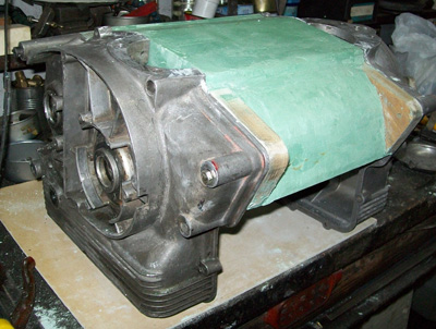
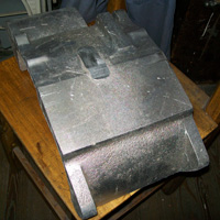
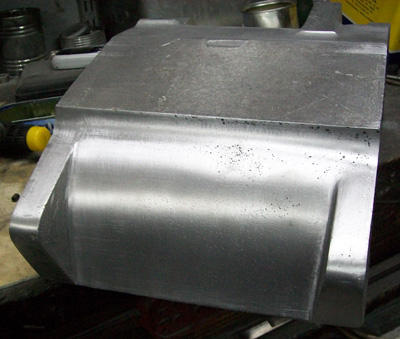
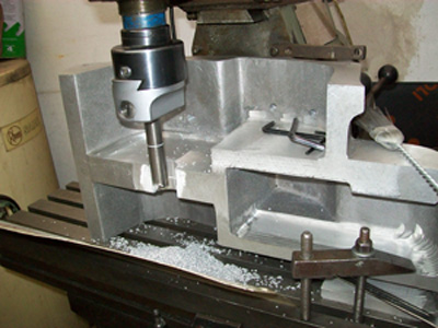
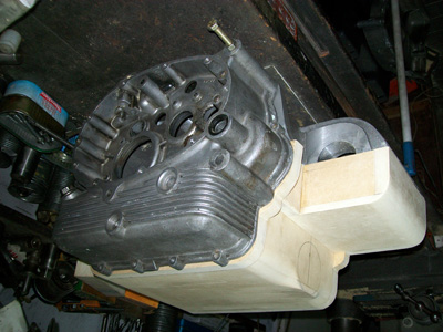
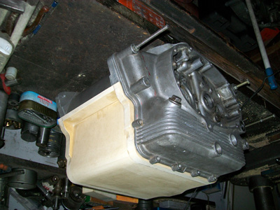
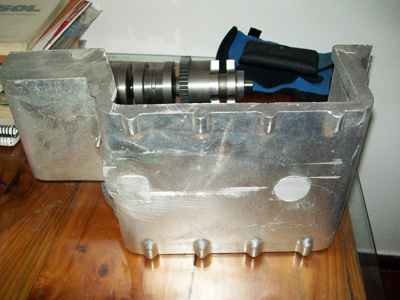
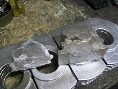
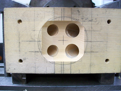
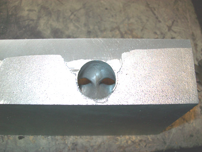
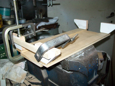
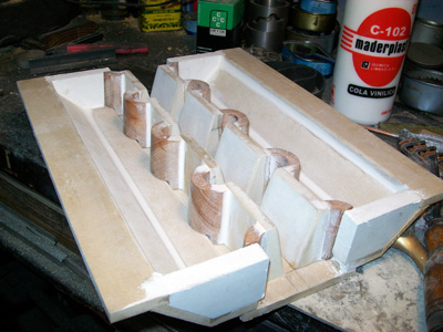
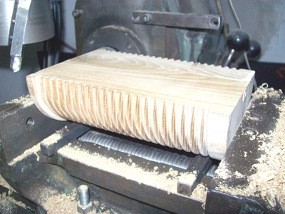
The block was the first to be done , I'd to lodge what I was going to build and then I start from here . Got some kgs. of chalk and start with the sculpture . Place some threaded bars for space the original block's halves and slowly start spreading layer over layer of material .
|
|---|
 |
 |
 |
|
|---|
 |
 |
|---|
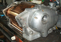
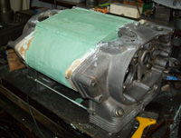
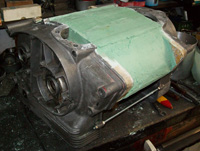
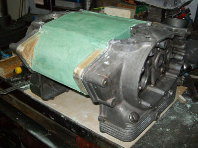
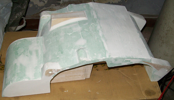
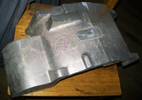
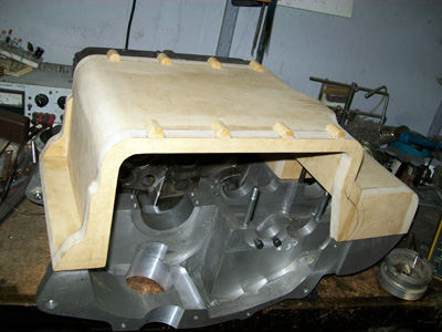
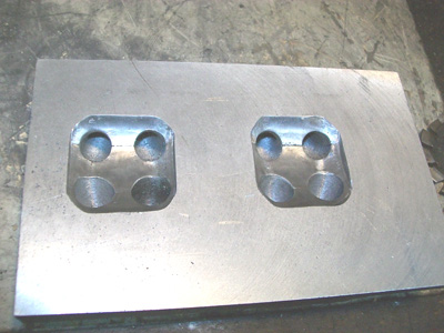
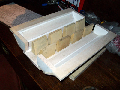
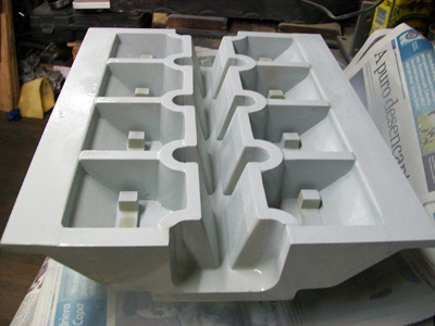
| When it was completely dry , I dismountthe model and gave finishing to the surface . |
|---|
 |
|---|
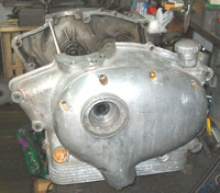
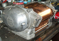
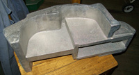
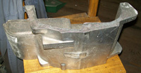
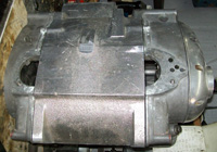
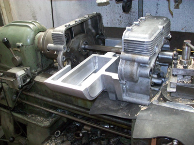
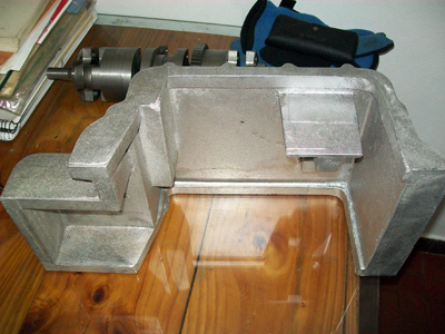
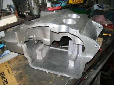
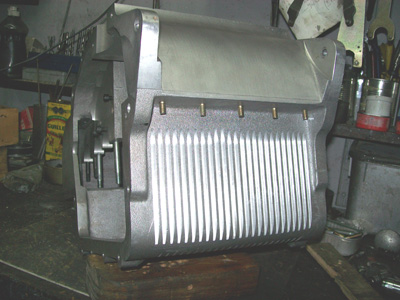
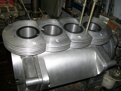
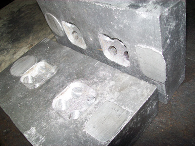
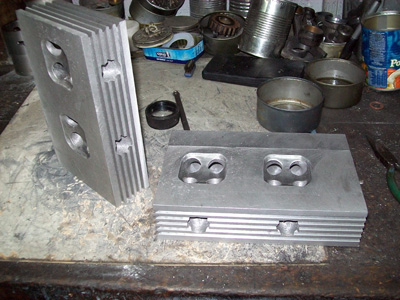
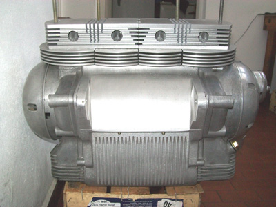
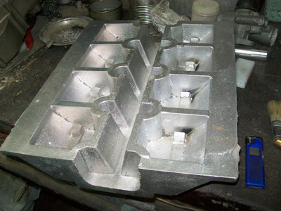
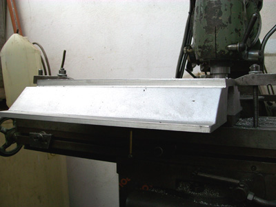
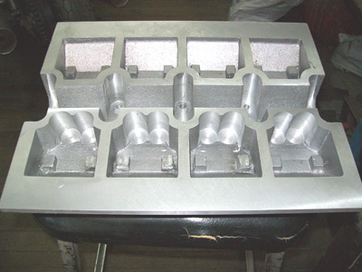
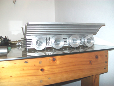
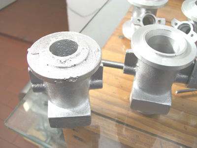
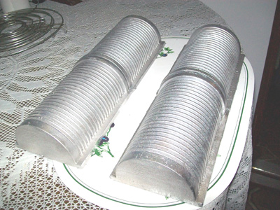
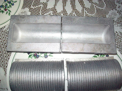
I took it to cast , and at the next week was ready the same shape but in alluminium . The surface were rough . but thoroughly I polish it all around before , to take it to the milling machine . |
|---|
 |
 |
 |
 |
|---|
 |
 |
|---|
 |
|
|---|
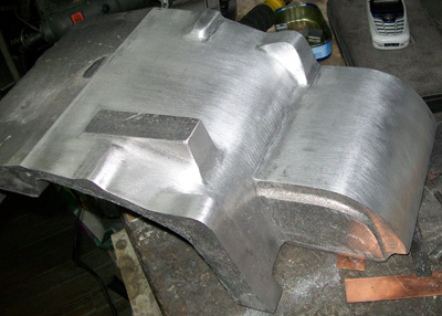
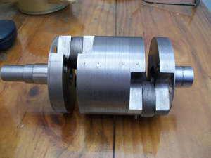
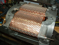
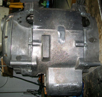
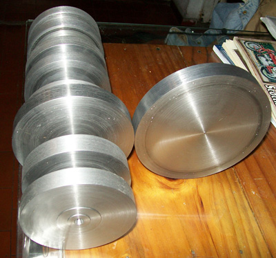
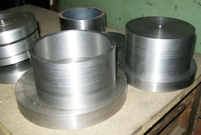
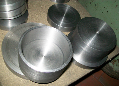
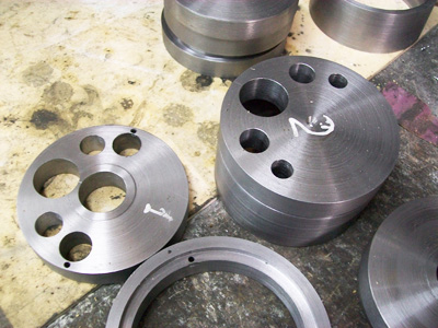
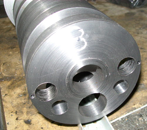
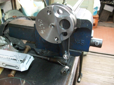
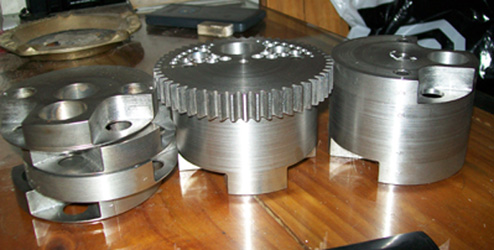
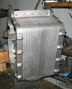
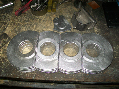
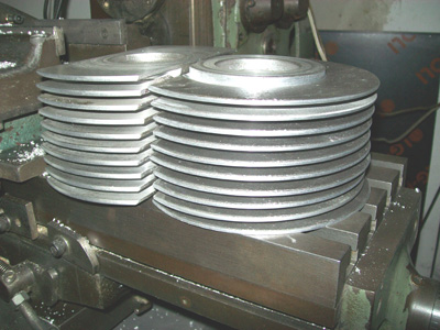
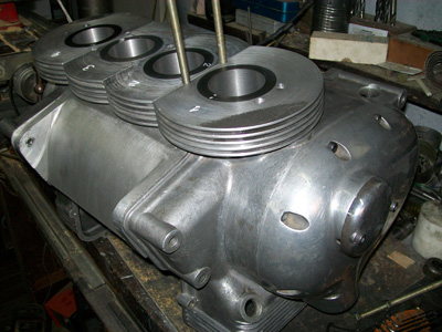
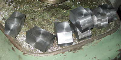
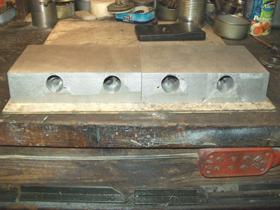
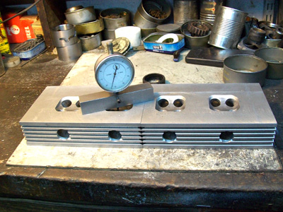
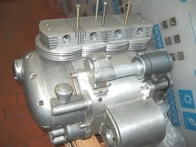
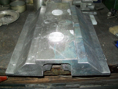
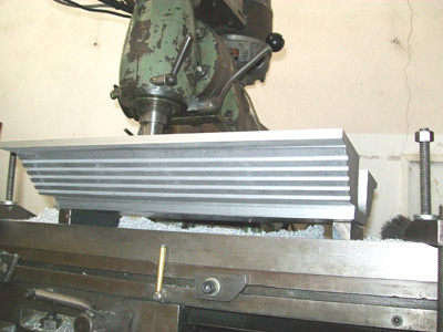
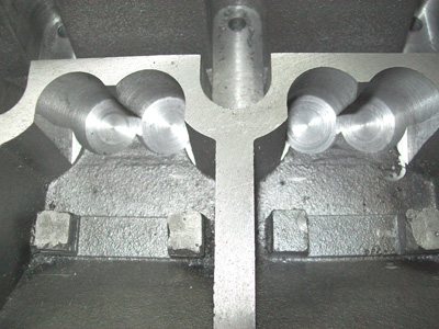
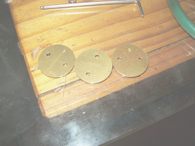
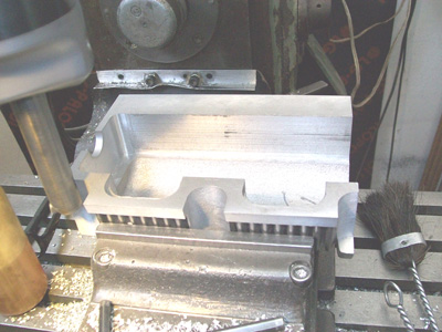
Milled out the excedent material and made the sides parallels . By another side I'd ready the nine chromo-nickel disk and start the job of mechanizing and assemble the crankshaft . Lathe the disks , and drill the centers up to the centime . |
|---|
 |
 |
|---|
 |
 |
|---|
 |
|
|---|
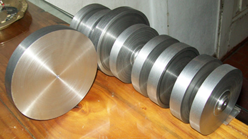
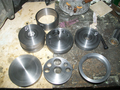
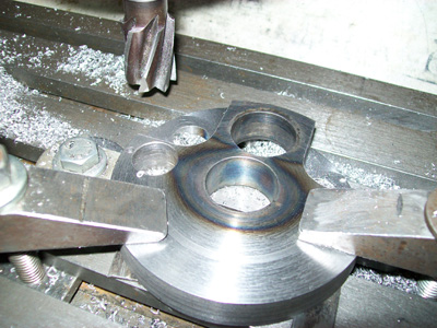
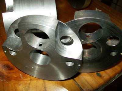
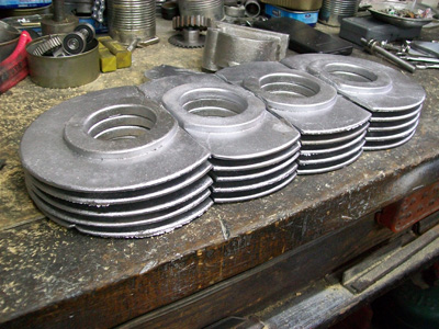
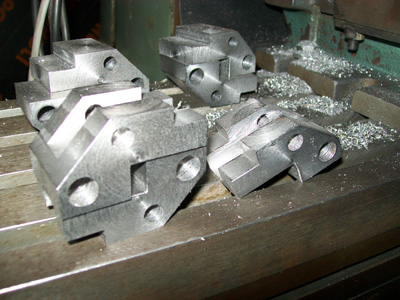
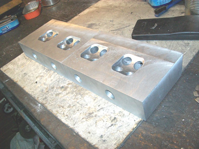
| Build the spacers and the extremes , drill the holes for make the disks more lights and assemble the conjunct . |
|---|
 |
 |
|---|
 |
 |
|---|
 |
|---|
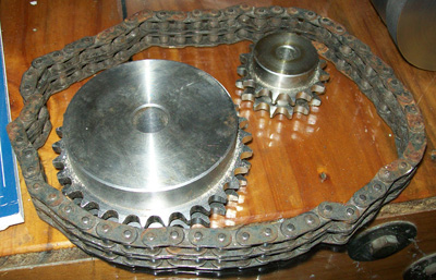
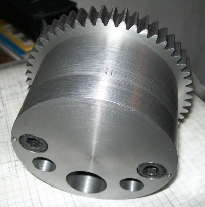
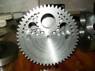
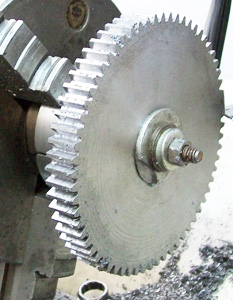
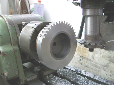
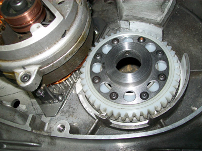
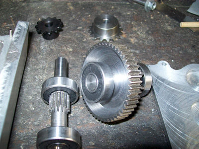
| Mill up the primary tractor gear . |
|---|
 |
 |
|---|
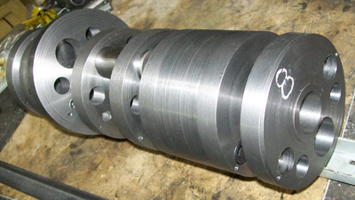
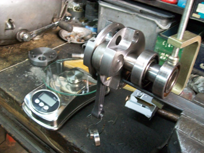
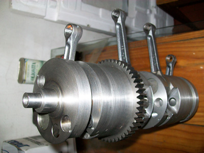
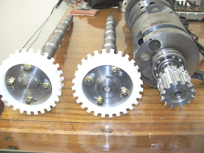
| When I'd all the discs and connecting rods with pistons set with me , with the digital scale I balance all four conjuncts individually . |
|---|
 |
 |
|---|
 |
 |
|---|
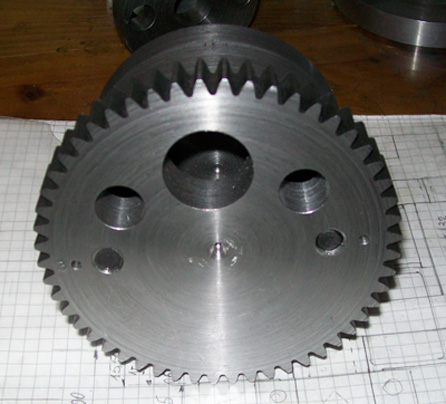
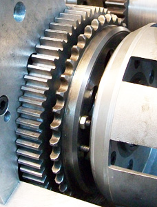
| Wich was more difficult to balance was the tractor gear , with drill bit and drlling blind holes up to 1mm from the bottom , to make sure the fluid lightness of the lubrication . |
|---|
 |
 |
|---|
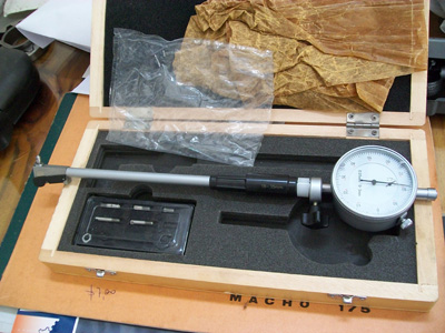
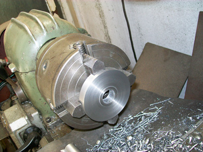
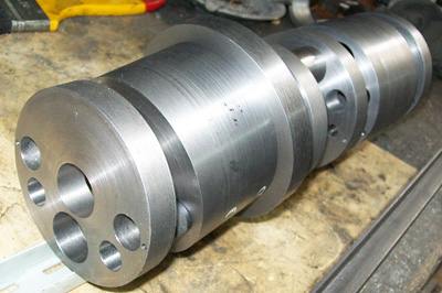
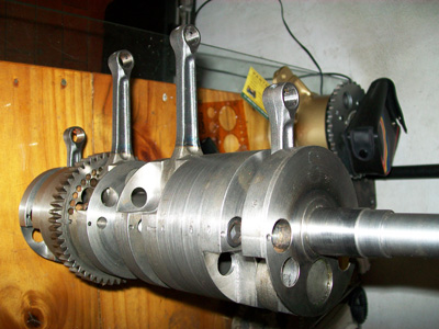
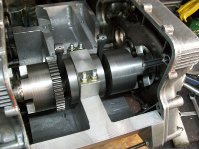
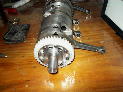
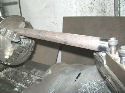
I assemble the crankshaft with the press and after came the hardest job , to align it ! . For left it properly were many hours to go and came from the press to the lathe carrying the dial-gauge , but when all this was finish and it turn smooth , I forgot the time it took me . |
|---|
 |
 |
|---|
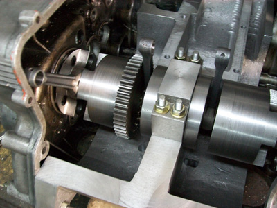
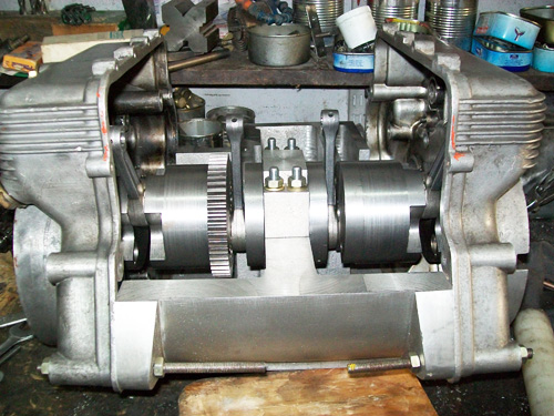
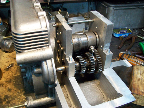
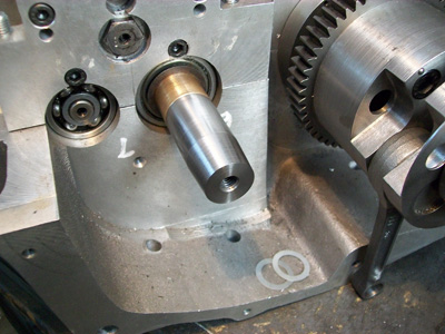
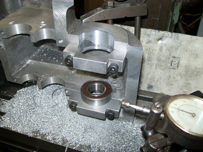
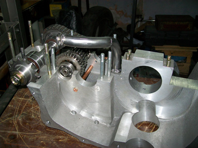
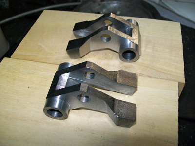
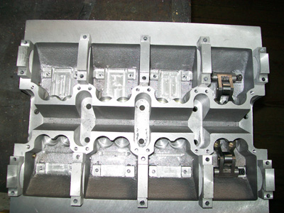
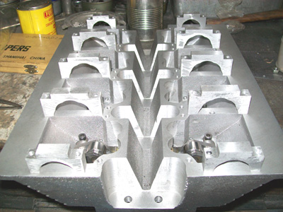
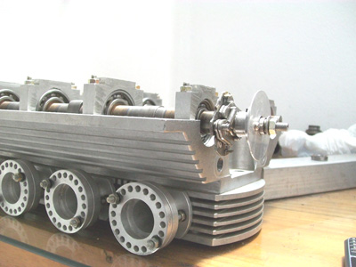
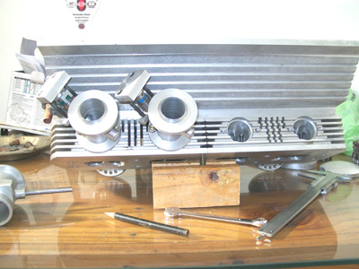
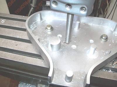
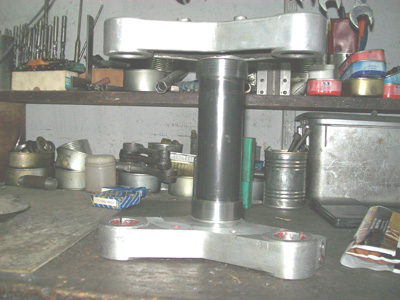
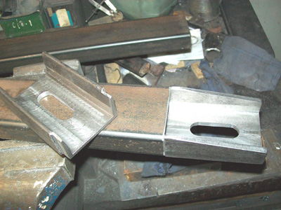
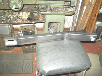
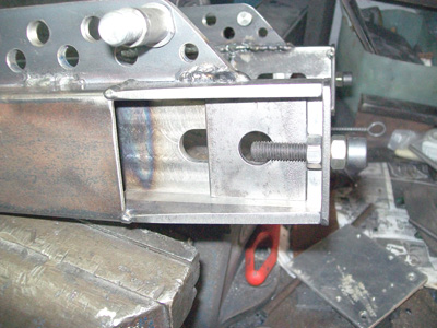
| For install the conjuncts at the half superior block , I start for mechanize the holdings supports beds for the crankshaft . |
|---|
 |
 |
|---|
 |
 |
|---|
 |
|---|
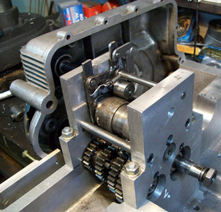
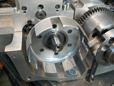
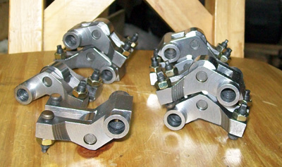
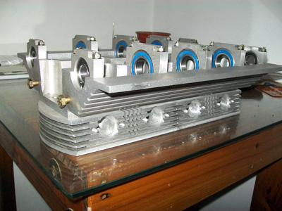
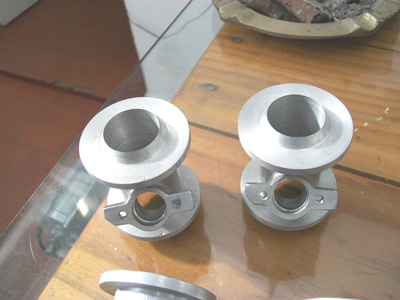
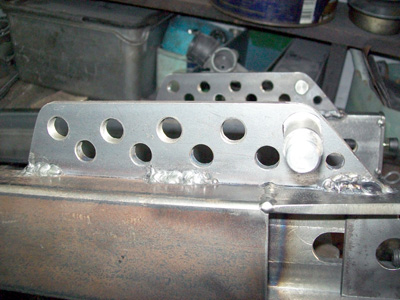
| Built the models for the gear gox supports and when had it the alluminium parts , make it square and mechanizing the bearings holders . |
|---|
 |
|---|
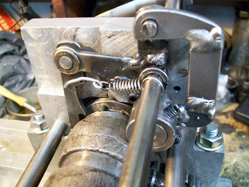
The selector came was assembled on a bearing on the side of the shifting pedal and the original selector system by gear with cricket , was replaced by the more actual system with pins and trigger . Built all the lever system with welded SAE 1020 plates which finally look nice to me . |
|---|
 |
 |
|---|
 |
|---|
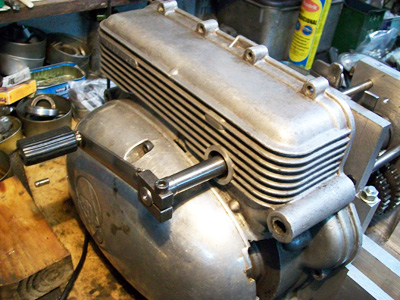
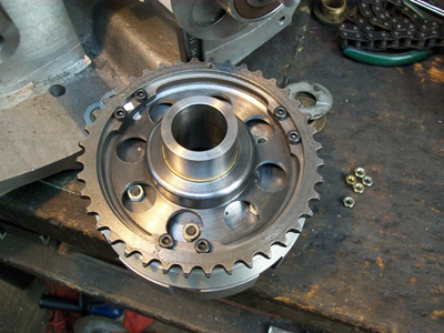
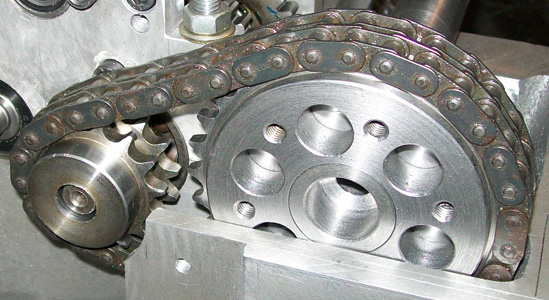
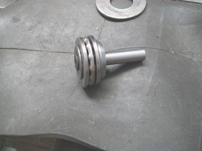
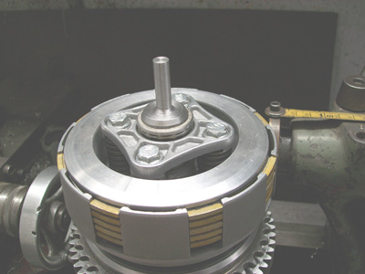
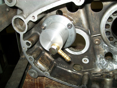
| Assemble the clutch and lathe off a prolongation for the shaft with the intention of place in , between the clutch and primary gear , the free wheel system from the starting system . |
|---|
 |
 |
|---|
 |
 |
|---|
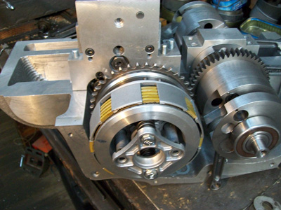
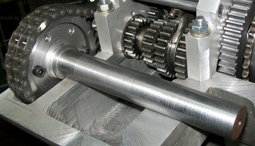
Mill out the missing primary gear , alighted the wheels and assemble the conjuncts , after diassemble it again for mechanizing the key holders and this parts was ready . |
|---|
 |
 |
|---|
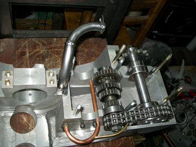
Make ready the intermediate shaft of the gear box power take off , alighted everything as much as possible . Mechanize the supports at the block and mount the shaft . |
|---|
 |
|---|
 |
|---|
 |
 |
|---|
 |
|---|
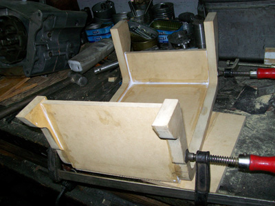
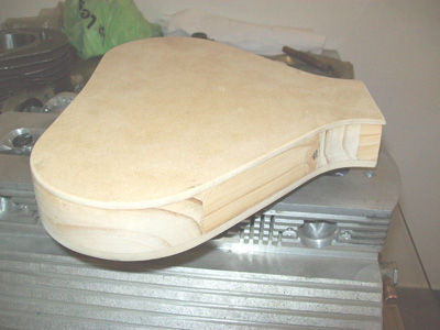
The lower half of the central block was the best site for place all the lubricant mechanism together with it pipes , by the other side the best place to put the oil filter I found was behind , just below the PTO (Power Take Off) shaft . The oil pump is driven by the crankshaft itself and attached to the vertical bulk head . So after , I began with the wooden model for cast the lower half of the block . |
|---|
 |
 |
|---|
 |
 |
|---|
| When got the part in aluminium , then I mechanize it as I'd draw it , adjusting it to the upper part . |
|---|
 |
 |
|---|
 |
 |
|---|
| Together with the normal and logic lubricant circuit over the box gears , I did mount a flute with calibrated holes over each pair of gears and a extension for able to lube the PTO reduction gear . |
|---|
 |
 |
|---|
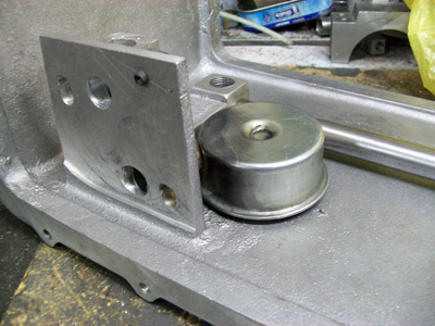
| I calculate and build the oil pressure regulating valve and the suction bell . |
|---|
 |
|---|
| I drew and builtthe pushing rod and the hydraulic actuator for the clutch system . |
|---|
 |
 |
|---|
 |
|---|
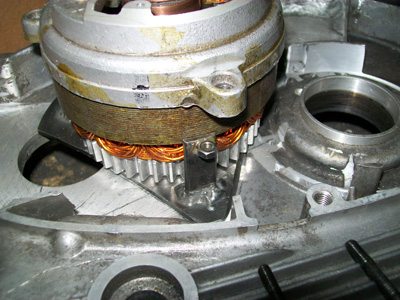
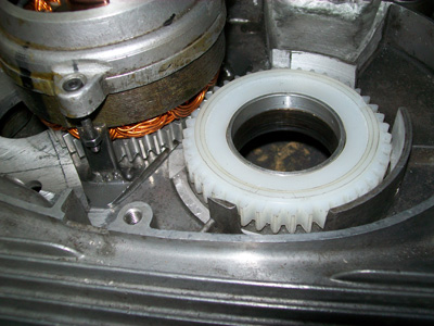
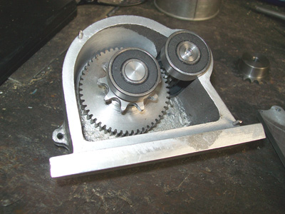
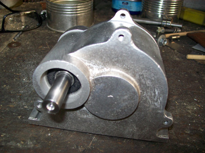
| For the electric current generator , the most practical transmision that I found was by means tooth gears . Built off the generator's one in aluminium , wich will be supported by ball bearings , and in poliamide the driving gear for the crankshaft . |
|---|
 |
 |
|---|
 |
 |
|---|
 |
|---|
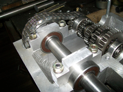
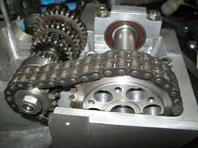
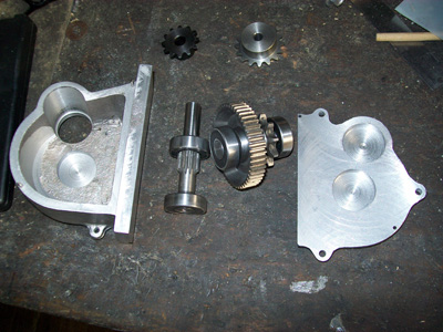
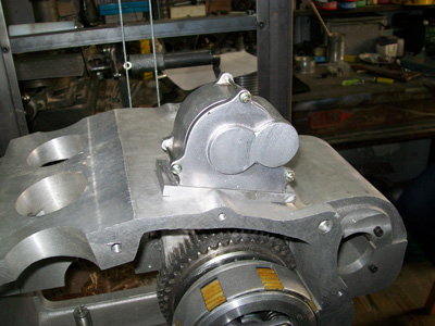
For the Electric Starting System , I cut a channel at the block for pass the transmission chain . Design the case for lodge the tooth gears , when Igot it , I built it and cut the gears . |
|---|
 |
 |
|---|
 |
 |
|---|
 |
 |
|---|
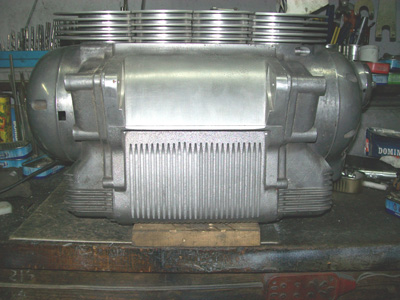
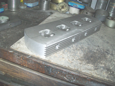
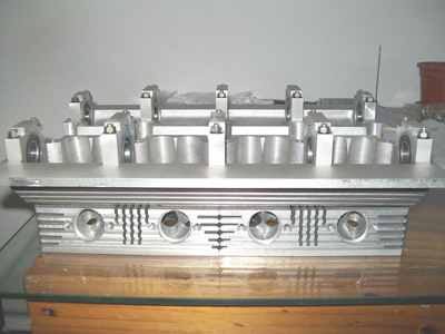
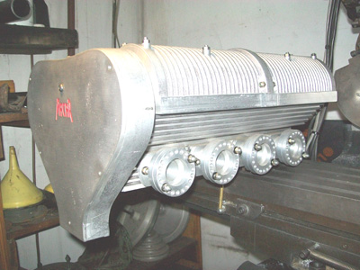
| For a better cooling of the engine , fins were cut at the front and rear part of the lower block half , with the intention of improve the lubeoil cooling . |
|---|
 |
 |
|---|
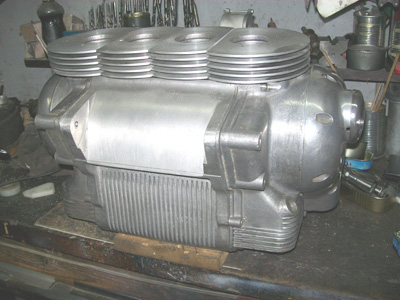
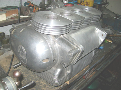
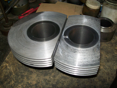
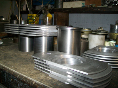
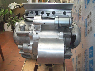
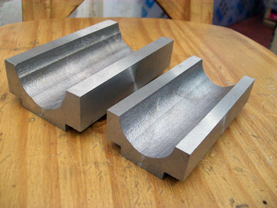
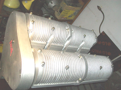
| With the design of the heat disipators of the cylinders , I built a wooden model , and took it to cast in aluminium . When got it back , I adjust it the conjunts of each cylinders . |
|---|
 |
 |
|---|
 |
 |
|---|
 |
 |
|---|
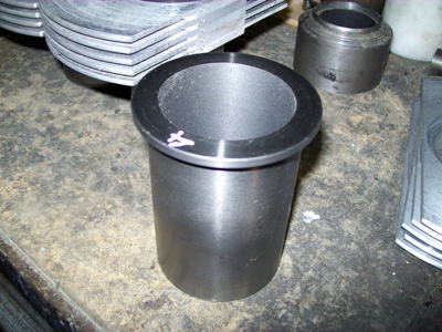
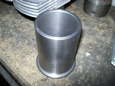
| After a long search and patient wait , I found who cast in centrifugate and with the proper Brinell hardness needed , the cylinders liners . |
|---|
 |
 |
|---|
 |
 |
|---|
 |
 |
|---|
|
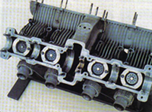
I start with the redesign of the cylinder covers that I'd built in the past with two valves and bell pushrods , changing it by a new one with four valves per cylinder and rocker arms . Obviously a fail long search and also after disturb a lot of close peoples trying to found the rocker arms that better adapt to my design of cylinder cover , find out the most healthy way was design it , buy the materials and built'm . |
|---|
 |
 |
|---|
 |
 |
|---|
| When had ready the noyos boxes for the ducts of the cylinder covers , sent everything to cast . |
|---|
 |
 |
|---|
 |
 |
|---|
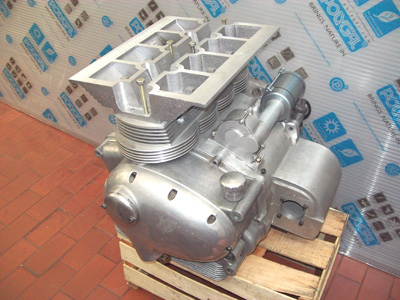
| And start to shape the raw blocks . |
|---|
 |
 |
|---|
 |
 |
|---|
 |
 |
|---|
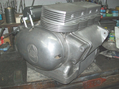
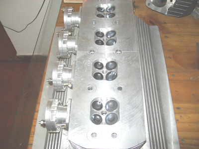
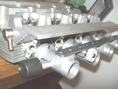
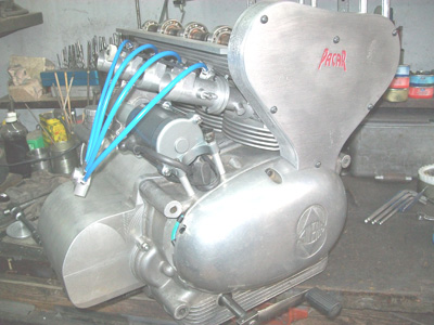
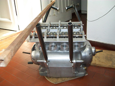
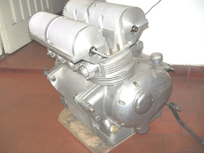
| After , to put everything together and enjoy the view . |
|---|
 |
 |
|---|
The camshaft's holders was a complete deffy because the precission and the contraction of the material . Having the valves and the rockerarms on hand , I sat down to design it and after ounce again start gluying small woods . |
|---|
 |
 |
|---|
 |
 |
|---|
| Ounce the parts were all in alloy , starts the milling machine trip . |
|---|
 |
 |
|---|
 |
 |
|---|
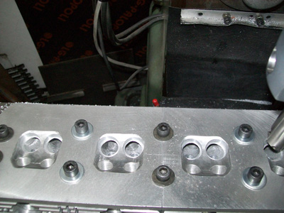
| After finish to square it , had already the shape of a cylinder cover . |
|---|
 |
 |
|---|
 |
|---|
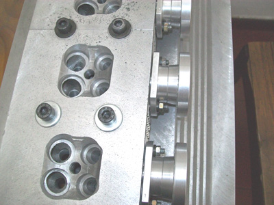
| The spring seats . |
|---|
 |
 |
|---|
| The rockerarms seats . |
|---|
 |
|---|
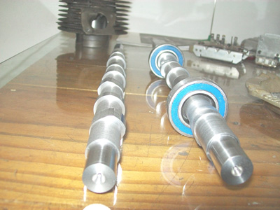
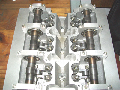
| Next step was to mechanize the ball bearing seats for the camshafts , previous construction of the correspondig covers . |
|---|
 |
 |
|---|
 |
 |
|---|
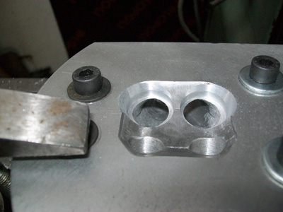
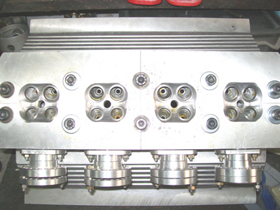
| The drilling for the seats valve's guides at the cylinder cover conjunt . |
|---|
 |
|
|---|
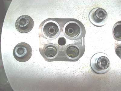
The drilling , threading and milling for the sparkplugs . |
|---|
 |
|---|
| Time being for the ignition I chose the optical trigger system with a simple electronic mainly for reduce the noises . |
|---|
 |
 |
|---|
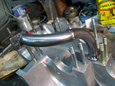
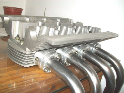
For the injection I´d decide for the alredy proved system for the four cylinders , but with a diferent curve . I built the connection sockets for the exhaust pipes bends and fit in place . |
|---|
 |
 |
|---|
| The valves seat were mechanized from round bar raw material . |
|---|
| I mechanize the housings of it at the aluminium cylinder cover and stick in place . |
|---|
 |
|
|---|
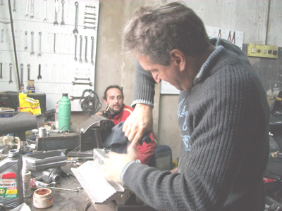
| The angles of the seats I trust to Adrian , wich were manually milled and remain very nite . |
|---|
 |
 |
|---|
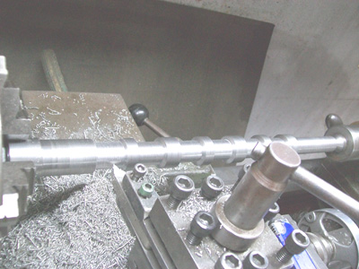
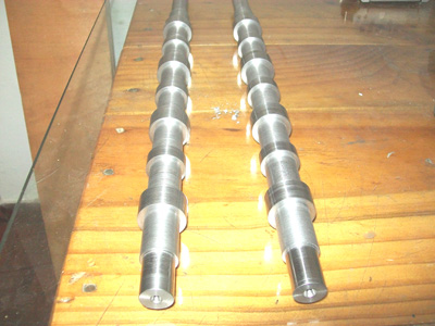
| I did perform some calculations for the camshafts and draw it , after were lathe mechanized out from a chrome-niquel steel bar . |
|---|
 |
|---|
 |
 |
|---|
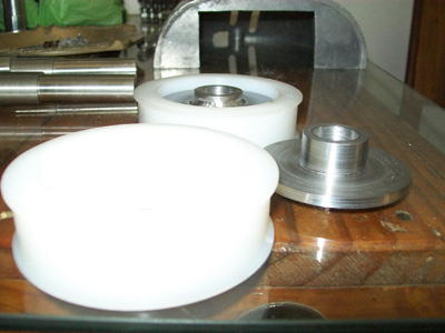
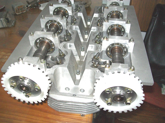
| For the distribution gear wheels material at the camshaft command , some light resine was choosen , and aluminium for the side of the cranckshaft , with a key . |
|---|
 |
 |
|---|
| The original centrifugal advance was kept but with limiters installed and the springs tension was adjusted in consequence . |
|---|
|
|---|
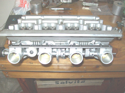
The design of the injection nozzles was completed with the corresponding independent adjustements . I mechanized the round brass slices for the butterflies and the shafts for its were milled . I fix the conjunct on an iron bar and place the ralentí adjustement stopper also with the bowden cable stopper for the action of the throttle wheel . |
|---|
 |
 |
|---|
 |
 |
|---|
 |
 |
|---|
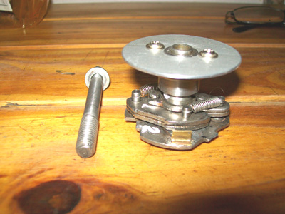
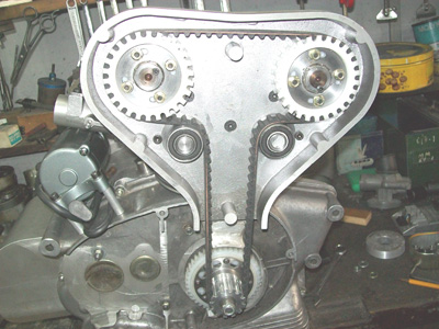
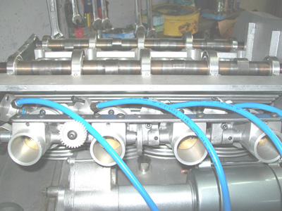
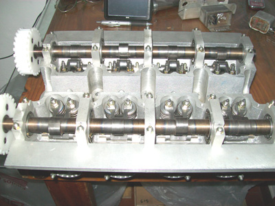
| Assemble mount the rocker arms with the tappet clearance adjusting screws , the camshafts and the excentrical distribution belt tensioning device on place on the dust protection box . |
|---|
 |
 |
|---|
 |
 |
|---|
 |
|---|
| I did design and mechanize the connectors for the gasoline feeding lines because the ones I found at the market were very bulky . |
|---|
 |
 |
|---|
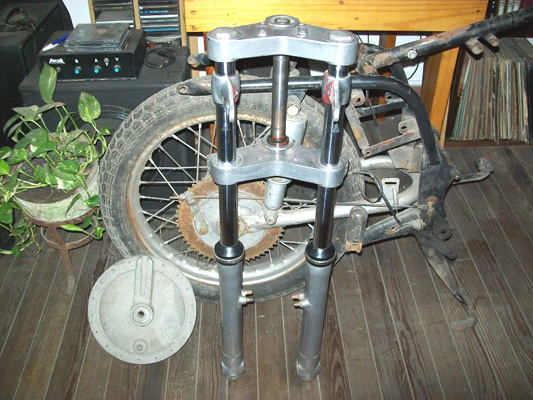
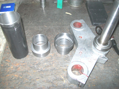
| I got a front fork , license Marzocchi , and around this one , design the driving pipe and shaft for house conical bearings , just because I like this system . Has an upper and a lower bearings holders with O'rings seal , for hold the grease inside . |
|---|
|
|---|
 |
 |
|---|
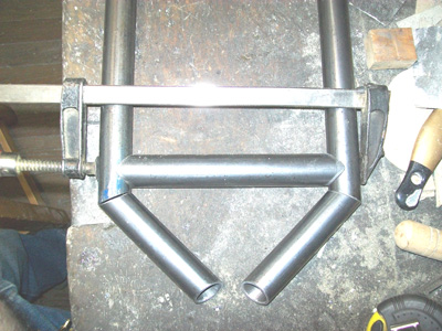
| The frame design came out in one part from my personal experience and the other from the technical files I join at the lenght of the time . The next step was to cut present and weld the pipes . |
|---|
 |
 |
|---|
 |
 |
|---|
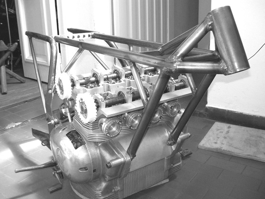
| The frame is in two parts , the rear section goes bolted to the front section , this makes much more easy the assembling and dissassembling for remove the engine . |
|---|
 |
 |
|---|
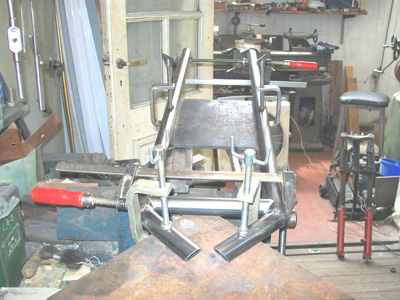
| After this , I prepare and weld in place the stiffeners , for rigidize and make the conjunt more strong . |
|---|
 |
|---|
| The rear swing arm (wich was built on rectangular welded pipes) swings on ball bearings and also five position fittings , were place for change the attack angle of the shock absorvers . |
|---|
 |
 |
|---|
 |
 |
|---|
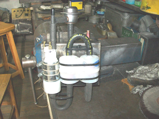
| The space behind the engine , was good enough for place the battery and the combustible pressure system . |
|---|
 |
|---|
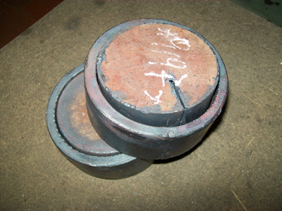
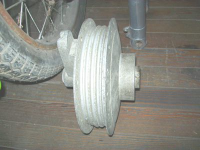
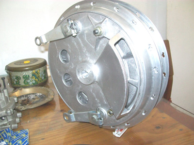
| Again and trough the hands of a friends , arrives a competition rear brake drum , built here in Argentina long time ago . |
|---|
 |
 |
|---|
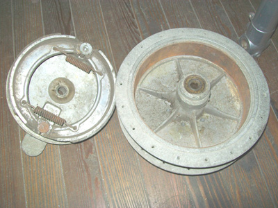
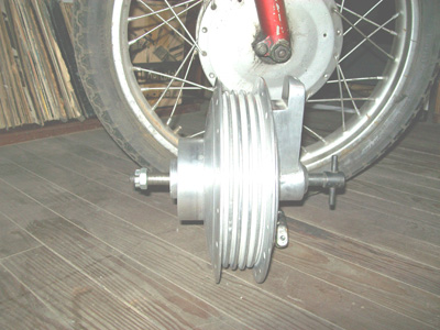
| I clean and repair , making it ready to be use , when finish this part was shining . |
|---|
 |
 |
|---|
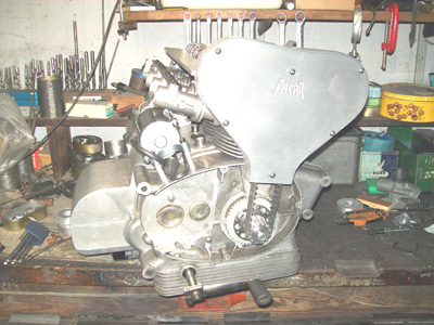
| Next I mecanized the parts that comply the ignition system and did assemble them on place at the camshaft side . |
|---|
 |
|---|
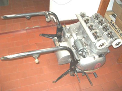
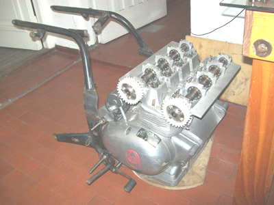
| Mount the rocker arms the camshafts and like when I was a kid , I enjoyed the coordinated valet of the 1-3-4-2 of the valves . |
|---|
 |
 |
|---|
 |
|---|
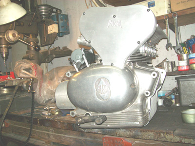
| After two failed attemps with the models of the valves covers , like it use to be I succseed with the third . |
|---|
 |
 |
|---|
 |
|---|
| Here starts a long trip through very small mechanize processes , revision of the drawings done long time ago and meditation times until find every and any solution for every surprise arose . |
|---|
 |
 |
|---|
 |
 |
|---|
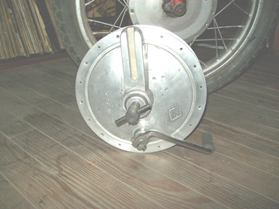
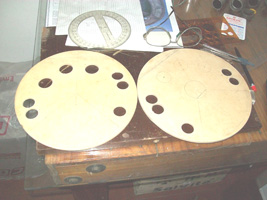
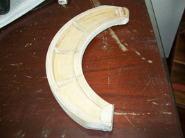
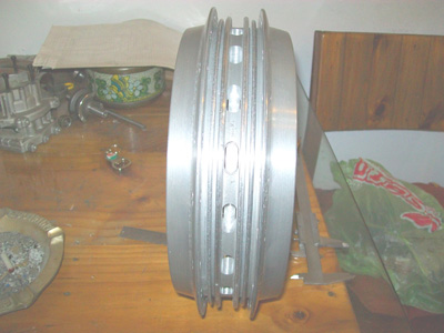
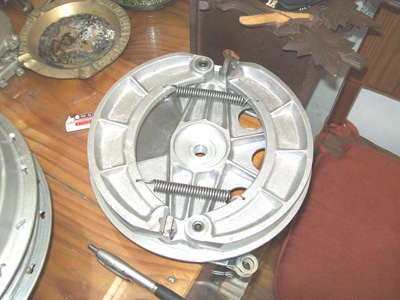
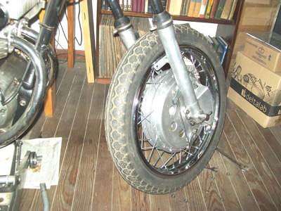
When rhe time to give shape to the front wheel brake , it seem to me not very coherent to reedit my old Gilera 300 disk type . For complete the armony of the conjunt , the front brake must be a drum type one and a huge one for match the performance of double disc system . I liked very much the four cams drums , but this were very expensive to reach . After I join all the documentation (pictures included) and draw my own plans inspired in one "predisc" era . Again the wooden molds for casting were done , built the inserts and send for cast in aluminium . |
|---|
 |
 |
 |
|---|
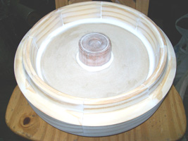
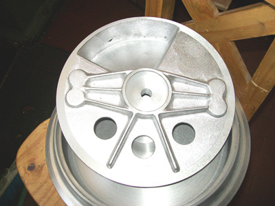
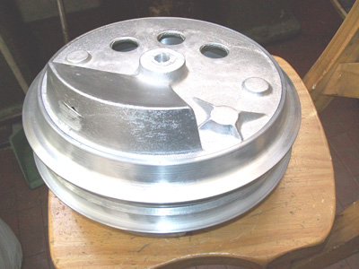
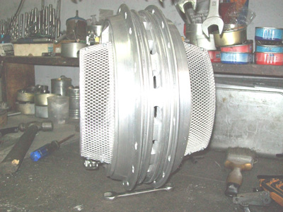
| Ounce back at home I start mechanizing of a 230mm efective diameter drum , with a central forcer cooling . |
|---|
 |
 |
|---|
 |
 |
|---|
 |
 |
|---|
 |
 |
|---|
 |
|---|
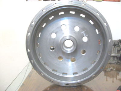
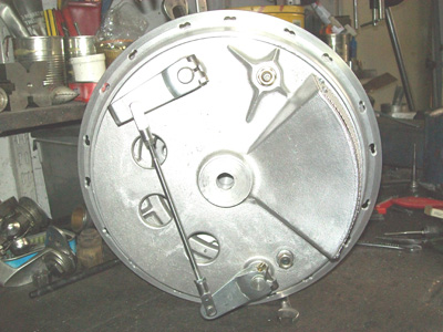
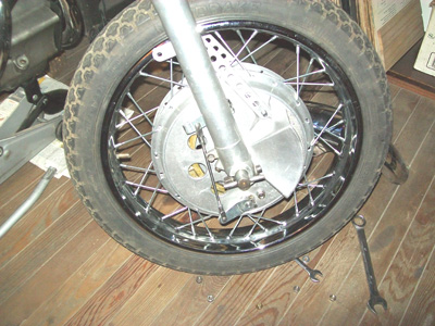
| The spokes anchor system is fast release for easy mounting , and is for 36 spokes . The central hub was mechanized for the fork in readiness . |
|---|
 |
 |
|---|
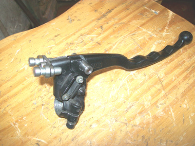
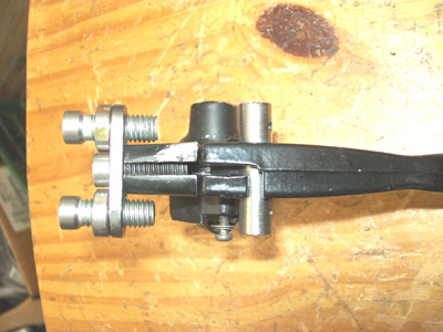
For help to finance this project , this four cams drum brake is put to sale , with the options for 36 or 40 spokes , and for 15 or 17mm of shaft diameter , for anybody who has some similar project . For action the brake system the problem was solve with a commercial lever , a prototype of double adjusting at the handle bar like at the old scool . |
|---|
 |
 |
|---|
| To be continued !!!!! |
|---|
Don't hessitate to phone me in case o mail , if you find out something that you don't like or seams no good and can be improved . I'm not only work in my bikes but also can develope anything you want for your machine , the workshop is in my home . |
|---|
Fone : 4584 - 7254 Cel .: 15 - 3045 - 8197 or 11 - 5913 - 4327 E-Mail : crupaes@yahoo.com.ar |
|---|
| Contact : Carlos Paes |
|---|